
12V DC Motor Small Sizing Tool & Engineering Guide
Enter shaft torque and speed to estimate power, running current and a candidate 8–28mm motor envelope. Confirm the actual winding and drive ratings before selection.
Published 2026-10-22 · Sources checked 2026-10-22 · Evidence & limits
Engineering sizing results
Candidate — supplier confirmation needed
Planning candidate only. Confirm the actual motor, controller, thermal cycle and transmission ratings with the supplier.
Submitted: 2.2mN·m · 6500RPM · 12V · Ø≤16mm · S1 100% · Coreless precious metal brushed
Shaft mechanical power
1.497 W
Calculated from torque × speed
Estimated running bus current
168.6 mA
At 12V; excludes controller losses
Assumed system efficiency
74%
Motor × gear efficiency; not measured
Modeled average temperature rise
14.7 K
Above ambient; peak temperature unknown
Ø16 mm planning candidate
Diameter only; allow mounting tolerance and verify total motor + gearhead + encoder length. Values do not specify a purchasable motor.
Direct-drive candidate
Motor operating point: 2.2mN·m at 6500RPM. Assumed motor / gear efficiency: 74% / 100%.
Average motor / gear losses: 0.526W / 0W. Average motor loss × assumed thermal resistance. Gear heat is reported separately. Actual winding peak and ambient temperature remain unverified.
Drive diagnostics and unknowns
- Stall protection time: unknown
- Stall time is unknown. Obtain the actual winding limit, driver current limit and transient thermal model before setting protection.
- Brushed winding reference only
- N/A — no applicable winding reference.
- PWM reference ripple
- N/A N/A: actual winding inductance and driver topology are required. BLDC phase ripple cannot be inferred from DC bus current.
- Tangential force: 0.367N
- 2T/d at a 12mm pulley. Total radial bearing load and bearing capacity: unknown.
Assumptions and limits
- Screening assumptions only: no selected winding, torque-speed curve, gearbox torque rating or complete assembly dimensions have been validated.
- Assumed motor efficiency 74%; gear efficiency 100%; motor-to-ambient thermal resistance 28 K/W. Controller losses and auxiliary current are excluded.
- Temperature rise is an average-loss estimate, not a permissible winding temperature or a safety approval. Ambient temperature, mounting and transient peaks remain unknown.
- Tangential force is 2T/d only. Actual belt radial load also needs pretension and geometry; gear forces need pressure angle. Bearing fit requires the OEM load rating at the actual overhang and speed.
Decision summary: what the screen can tell you
1. Winding before diameter
Check the operating curve
Rated torque, no-load speed and peak power are different operating points; see the source-linked reference matrix.
2. Size the complete drive
Count motor + gear losses
Reduction changes speed and torque; output torque is still limited by the gearhead rating.
3. Leave unknowns visible
Verify heat and shaft load
Average losses cannot establish peak winding temperature, stall duration, bearing capacity or application life.
For supplier-specific evidence, use the reference matrix. For reproducible assumptions, use the planning model table. The examples below demonstrate calculations rather than tested product performance.
Reproduce a small 12V motor sizing example
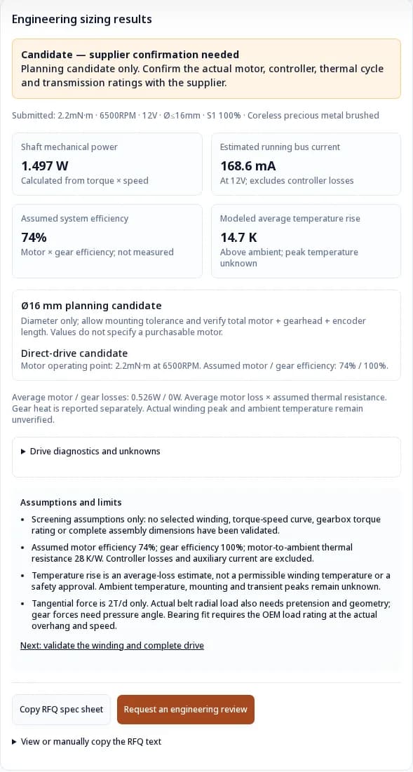
This software capture uses 2.2mN·m at 6,500 RPM, 12V, a 16mm diameter limit, S1 continuous duty, precious-metal brushed commutation, a 12mm pulley and 32kHz PWM. Shaft power is 1.497W; with the assumed 74% motor efficiency and direct drive, estimated bus current is 168.6mA. Enter these values above to reproduce the result.
1. Define the envelope before selecting a frame
This tool covers cylindrical motor-body classes from 8mm to 28mm. It chooses the largest modeled diameter at or below the input limit; a 9mm limit therefore uses the 8mm planning class. Motor length, shaft protrusion, mounting tolerances and accessory space are separate requirements.
Maximum body diameter → Candidate at or below limit → Check full assembly drawing
A rectangular gearmotor also needs corner clearance in a circular bore. Compare the actual drawing with the mounting volume. Pololu dimensional reference.
2. Winding resistance matters as much as nominal voltage
A nominal 12V label does not specify loaded speed or torque. Within a given magnetic design, winding turns and conductor size change electrical resistance and the torque/speed constants. A custom winding can move the operating curve, but it does not remove the thermal and mechanical limits of the frame.
Actual voltage range → Winding curve and resistance → Loaded current and losses
For a brushed motor, use V ≈ I·R + k_e·ω, and torque ≈ k_t·I after accounting for friction. The power-based current estimate above cannot replace this winding check. Construction and motor characteristics.
3. Direct drive or reduction: preserve speed and torque together
The tool considers reduction below 2,500 RPM or above a planning torque threshold. Those are screening rules. Low-speed direct drive can be appropriate with a suitable winding, feedback and cooling. For a geared candidate, use n_motor = ratio × n_output and T_motor = T_output / (ratio × gear efficiency).
Motor torque and speed → Ratio and gear losses → Required shaft operating point
On small screens, swipe the table horizontally. Keyboard users can focus and scroll it.
| Stage estimate | Ratio band | Assumed efficiency | Still needed |
|---|---|---|---|
| 1 | Up to 6:1 | 86% | Input speed and output torque limits |
| 2 | >6 to 36:1 | 74% | Efficiency at actual torque and speed |
| 3 | >36 to 216:1 | 62% | Thermal behavior, backlash and life |
| 4 | >216 to 1,296:1 | 50% | Available catalogue ratio and load capacity |
Ratios are estimates, not stocked options. The tool reports the actual required motor speed and flags values above its 35,000 RPM planning ceiling. It does not cap speed to make a design appear to fit. The Pololu family illustrates why higher ratios do not remove gear strength limits.
4. Choose commutation from the application requirements
Noise, duty and lifetime target → Brushes or matched BLDC drive → Test the installed assembly
On small screens, swipe the table horizontally. Keyboard users can focus and scroll it.
| Architecture | Useful starting point | Cost / complexity | Verify before selection |
|---|---|---|---|
| Coreless precious metal | Low inertia and low contact friction | Simple two-wire motor; specialist construction | Contact current, starts, brush wear and PWM behavior |
| Iron-core carbon brushed | Cost-sensitive mechanisms with simple electronics | Cogging and contact wear can matter | Starting torque, installed acoustic noise and thermal duty |
| Slotless BLDC | Applications where mechanical commutation wear is undesirable | Matched controller, sensing and drive tuning | Phase current, cooling, bearing life and starting/holding behavior |
Rotor construction and brush material are separate dimensions: carbon brushes can also be used in a coreless motor. The comparison represents three configurations, not all motor designs. Portescap construction reference.
5. Model average heat; verify peak winding temperature separately
Output power divided by gear efficiency gives motor shaft power. Dividing that by assumed motor efficiency gives motor electrical input. Motor loss is the difference between these two values; gear loss is separate. For S3, this tool multiplies both losses by on-time fraction and estimates average motor rise from motor loss × thermal resistance.
Motor loss during operation → On-time × thermal resistance → Average rise; peak unknown
Need a motor review before choosing these assumptions? Send your small 12V motor load and drawing for an RFQ review.
On small screens, swipe the table horizontally. Keyboard users can focus and scroll it.
| Diameter | Planning torque threshold | Assumed brushed efficiency | Assumed motor-to-ambient Rth | Evidence status |
|---|---|---|---|---|
| 8mm | 0.576mN·m | 55.00000000000001% | 89K/W | Torque / Rth anchored to cited reference; operating efficiency assumed |
| 10mm | 1.2mN·m | 62% | 60K/W | Illustrative assumptions; no selected motor |
| 12mm | 1.74mN·m | 68% | 50K/W | Torque / Rth anchored to cited reference; operating efficiency assumed |
| 16mm | 5.8mN·m | 74% | 28K/W | Illustrative assumptions; no selected motor |
| 22mm | 15mN·m | 80% | 19K/W | Illustrative assumptions; no selected motor |
| 28mm | 32mN·m | 84% | 13K/W | Illustrative assumptions; no selected motor |
For carbon brushed screening, assumed efficiency is 5 percentage points lower; BLDC is 3 points higher. These scenario adjustments are unvalidated, not measured technology advantages. Rise above 75K is flagged outside the model; this is not an insulation-class limit. Mounting, ambient, controller losses, start/brake cycles and pulse duration can change the outcome.
The standard configurations in the 0816 and 1224 sheets specify 85°C maximum winding temperature. Use the actual configuration. IEC 60034-1:2026 provides rating context; the public catalogue does not establish conformity of this tool or your application.
6. Tangential force is not a bearing load approval
The tool calculates F_t = 2T/d. With T in mN·m and pulley pitch diameter d in mm, the result is newtons. This is transmitted tangential force. Actual belt loads need pretension and direction; a gear mesh also needs its pressure angle. The bending moment depends on the distance from the support to the load.
Torque and pitch diameter → Pretension, angle and overhang → Compare OEM bearing rating
On small screens, swipe the table horizontally. Keyboard users can focus and scroll it.
| Torque | Pitch diameter | Calculated 2T/d | Unknowns |
|---|---|---|---|
| 1.2mN·m | 12mm | 0.2N | Belt tension, overhang, radial and axial rating |
| 120mN·m | 12mm | 20N | Gearhead bearing rating and external support requirement |
Do not use a generic “bushing OK” threshold. The 1224 sheet gives a dynamic radial load of 0.5N at 3,000 RPM and 3.4mm from the flange for its specified configuration. A bearing rating at another overhang or speed is not interchangeable.
7. PWM and noise: measure the drive rather than assuming silence
The optional diagnostic uses ΔI_pp ≈ V/(4Lf), a simplified 50%-duty brushed reference. It assumes continuous current and a fixed inductance. Winding resistance, back-EMF, freewheel mode and switching-frequency inductance can make the estimate unsuitable. No BLDC phase-ripple number is generated.
Actual winding L and driver → Measure winding current ripple → Check heat, EMI and acoustics
On small screens, swipe the table horizontally. Keyboard users can focus and scroll it.
| Question | What to measure | Decision consequence |
|---|---|---|
| Is frequency high enough? | Ripple at actual bus voltage, duty and load | Choose controller settings with the motor supplier |
| Would a choke help? | Heating, commutation and control-loop behavior | Added inductance has trade-offs; no universal choke value |
| Is the mechanism quiet? | Installed sound spectrum, gear mesh and mounting vibration | Ultrasonic switching alone does not guarantee silence |
See the Portescap PWM study for the assumptions and commutation trade-offs. Temperature rise, wear percentages and application life cannot be inferred from switching frequency alone.
8. Source-linked winding references and explicit data gaps
Checked 2026-10-22. OEM values below refer to named configurations; they are not universal diameter-class limits. Rated and no-load speeds are labelled separately. N/A means no verified selected winding or no stated value here. Planning-class rows do not borrow another manufacturer's identity.
On small screens, swipe the table horizontally. Keyboard users can focus and scroll it.
| Reference | Envelope | Torque | Speed | R | L | Evidence and limits |
|---|---|---|---|---|---|---|
| 0816 K 012 SR | Ø8mm × 15.9mm body | 0.576 mN·m rated | 2,960 RPM rated | 102Ω | 1,030µH | 12V, 22°C; specified mounting; not simultaneous peak values · Source |
| 10mm planning class | Ø10mm; length unknown | N/A — no selected winding | N/A | N/A | N/A | Illustrative sizing class only; obtain a current datasheet |
| 1224 N 012 SR | Ø12mm × 24.2mm body | 1.74 mN·m rated | 8,330 RPM rated | 18.2Ω | 220µH | 12V, 22°C; actual assembly and mounting still required · Source |
| Pololu HPCB 12V, 100:1 example | 10×12mm rectangular gearbox | N/A — stall is not continuous | 330 RPM no-load output | N/A — not stated here | N/A — not stated here | 0.75A stall current; verify ratio-specific limits and dimensional drawing · Source |
| 16mm planning class | Ø16mm; length unknown | N/A — no selected winding | N/A | N/A | N/A | Illustrative sizing class only |
| 22mm planning class | Ø22mm; length unknown | N/A — no selected winding | N/A | N/A | N/A | Illustrative sizing class only |
| 28mm planning class | Ø28mm; length unknown | N/A — no selected winding | N/A | N/A | N/A | Illustrative sizing class only |
Do not multiply stall torque by no-load speed to size usable power. Check the simultaneous loaded operating point and the complete assembly drawing.
9. Three reproducible worked examples
These are illustrative calculations using the same model and presets as the tool. They are not tested customer deployments, medical performance evidence, or guarantees of the named frame's suitability.
Illustrative continuous dosing-pump load
Can a 12mm package deliver 1.2mN·m at 5,200 RPM?
0.653W shaft · 80.1mA estimated bus current · 1:1 ratio
Start with a direct-drive candidate. Check the selected winding curve at minimum bus voltage, pump starting torque and installed heat path. Smooth motor rotation alone does not establish smooth fluid delivery.
Still needed: Pump curve, starting friction, flow-pulsation measurements, total length and duty-temperature test.
Illustrative intermittent optical wheel
What does 20% on-time change for an 8mm drive at 0.45mN·m and 9,000 RPM?
0.424W shaft · 64.3mA estimated bus current · 1:1 ratio
Average heat falls, while instantaneous power stays the same. The reference motor is not approved at this simultaneous torque/speed pair; use its voltage-dependent operating curve. Check start/stop inertia separately.
Still needed: Load inertia, move time, braking current, pulse duration, settling error and peak winding temperature.
Illustrative geared robotic gripper drive
What changes when a 22mm drive must provide 120mN·m at 120 RPM?
1.508W shaft · 244.2mA estimated bus current · 66.7:1 ratio
A reduction stage moves the operating point toward a faster motor speed. Verify output torque and input-speed ratings, then specify a holding brake or rated current control if the mechanism must hold at zero speed.
Still needed: Gearhead torque rating, efficiency map, holding current, backlash, pinch-force control and controller phase-current limits.
10. A practical validation sequence
Define the same-shaft load → Match winding and gear ratings → Test installed duty and limits
- Record simultaneous shaft torque and loaded speed, including start, acceleration, braking and zero-speed holding requirements.
- Draw the full envelope and specify minimum/maximum bus voltage. Match a real winding curve to the operating point at the worst available voltage.
- If using reduction, choose an available ratio and verify motor speed, gear input speed, continuous/peak output torque and efficiency at load.
- Check bus and phase current, transient temperature, shaft forces and driver protection using supplier data. Average duty alone is insufficient.
- Prototype in the final mounting and enclosure; measure load, temperature, current, noise, wear and failure behavior against the application targets.
11. Risks, cost trade-offs and alternative paths
On small screens, swipe the table horizontally. Keyboard users can focus and scroll it.
| Risk | What goes wrong | Mitigation / alternative |
|---|---|---|
| Misuse of an estimated fit | A frame fits geometrically but cannot reach the loaded speed | Use the actual winding curve; change winding, enlarge frame or reduce load |
| Uncontrolled jam or holding load | Motor heats while output speed and mechanical power are zero | Validate current-limited protection and hold duty; review a brake or self-locking mechanism |
| Transmission overload | Ratio multiplies torque beyond gearhead capability | Check output/input ratings; use a larger gearhead or reduce torque |
| Cost and integration | Custom windings, encoders and BLDC control increase engineering effort | Quote the complete drive and validation scope; compare a standard brushed assembly |
| Shaft-load mismatch | Belt tension or overhang exceeds the published bearing rating | Review external support or another bearing arrangement against actual forces |
When results are outside the assumptions, reduce torque or speed, enlarge the motor envelope, or request a supplier review with the full load cycle. Do not resolve an overload by reducing the displayed duty percentage without checking peak temperature.
12. Engineering selection FAQ
Envelope and selection
What does “12V DC motor small” mean on this page?
This page screens 8–28mm motor diameters for compact mechanisms. “Small” is a search term, not a dimensional standard. The diameter limit does not include shaft extension, gearbox length, encoder or wiring space.
Are 6mm or smaller 12V motors covered by the calculator?
The current planning model begins at 8mm. For smaller envelopes, send a drawing, voltage range, shaft torque and speed for a manual winding review; the calculator does not extrapolate a fit.
Does the candidate frame identify a motor I can buy?
No. It identifies a planning diameter that fits the entered limit. Winding choice, length, mounting tolerance and performance must be checked against a current supplier drawing and torque-speed curve.
Is an N20 gearmotor the same as a cylindrical 12mm motor?
No. N20-style packaging can be rectangular, and gearbox dimensions and ratios vary. Check the complete drawing, including corner clearance, rather than treating the width as a cylindrical diameter.
Power, current and winding evidence
How is shaft power calculated?
Mechanical power in watts equals torque in mN·m times loaded RPM times π/30,000. Enter torque and speed at the same shaft and operating point; do not combine stall torque with no-load speed.
Is the displayed operating current a measured motor current?
It is a DC bus planning estimate: shaft power divided by assumed motor and gear efficiencies and supply voltage. It excludes controller and auxiliary losses. BLDC phase current can differ substantially from DC bus current.
Why does a 12V winding often have higher resistance?
A higher voltage winding for a comparable speed generally uses more turns of finer wire within the available space. Actual resistance depends on the selected winding, so frame size alone cannot determine it.
Can a nominal 12V motor run from a 3S lithium-ion battery?
Check the motor and controller across the actual pack minimum and fully charged maximum, under load. Supply variation changes available speed and current; a nominal voltage label does not establish temperature or lifetime margins.
Why is there no universal safe PWM frequency?
Ripple depends on winding inductance at switching frequency, bus voltage, duty and driver topology. Use the manufacturer guidance and measure current. This tool only shows a simplified brushed reference where winding data is available.
Heat, duty cycle and stall
Does S3 duty guarantee a safe peak temperature?
No. The calculator scales average motor losses by on-time fraction. Pulse duration, cooling time, starting losses, braking and initial temperature are missing, so it cannot predict peak winding temperature or certify an S3 rating.
Why is there no countdown to stall burnout?
A reliable time needs the actual winding temperature limit, current-limited driver behavior, initial temperature and transient thermal network. A generic 130°C assumption can be wrong. Request a tested protection limit rather than using a predicted safe delay.
Are winding temperature limits always 130°C?
No. Use the exact motor configuration and datasheet. Insulation classification alone does not establish the permissible motor operating temperature; magnets, adhesive, commutation and lubrication can impose lower limits.
What does the temperature-rise estimate include?
Average motor losses multiplied by an assumed motor-to-ambient thermal resistance. Gear losses are shown separately. Ambient temperature, installed cooling, controller losses and transient peaks are not included.
Gears, shaft forces and next steps
When does the tool suggest a gearbox?
It uses a planning rule when shaft speed is below 2,500 RPM or torque exceeds the selected frame assumption. These thresholds are not physical motor limits; low-speed direct drive may work with a suitable winding and controller.
Does a higher ratio always increase usable output torque?
No. Gear efficiency, tooth strength, shaft load and input-speed ratings can limit the assembly before the motor does. Check continuous and intermittent gearbox ratings at the actual operating point.
Is 2T/d the radial bearing load?
It is the transmitted tangential force at a pulley or pinion. Belt pretension, belt wrap and direction, gear pressure angle and load overhang are also needed for the actual radial load and bending moment.
Can I use a generic sleeve-bearing load limit?
No. Obtain the motor or gearhead load rating at the actual distance from the flange and operating speed. If the rating is insufficient, review external shaft support or a different bearing arrangement with the supplier.
Does BLDC automatically provide a guaranteed long life?
Removing mechanical commutation removes brush wear, but bearing life, cooling, electronics, contamination and load still require application tests. Choose on measured requirements rather than a universal hour figure.
What should I send for an engineering RFQ?
Send torque and loaded speed at the same shaft, bus voltage range, diameter and total length drawing, pulse and cycle timing, ambient temperature, shaft overhang and forces, controller limits, quantity and lifetime target. Include the tool assumptions with any copied estimates.
13. Sources, dates and scope of evidence
Sources checked on 2026-10-22. Manufacturer references support their named products and stated test conditions. Planning assumptions and worked examples are labelled separately. No independent application test, certification, lifetime or medical suitability assessment is claimed. For source corrections or method questions, contact the publisher.
- FAULHABER 0816 SR — 12V column, edition 2026-07-28 (PDF)
Specific 0816 K 012 SR reference at 22°C: winding data and rated operating point. Standard winding limit 85°C; optional 125°C version is a separate configuration. Does not validate another 8mm motor.
- FAULHABER 1224 SR — 12V column, edition 2026-07-28 (PDF)
Specific 1224 N 012 SR reference: resistance 18.2Ω, inductance 220µH, rated torque 1.74mN·m. Standard winding limit 85°C. Ratings depend on mounting and operating point.
- Portescap — Controlling Brushed DC Motors Using PWM (2019, PDF)
Brushed motor ripple, inductance, switching topology and life considerations. Frequency alone cannot establish ripple, temperature or service life. Added series inductance has commutation trade-offs.
- Portescap — Brushed DC Motor Basics
Ironless rotor construction, precious-metal and carbon-copper commutation, low inertia and bearing options. No universal brush-current or lifetime guarantee.
- Pololu — Micro Metal Gearmotors, HPCB 12V and dimensions
One N20-style family: rectangular 10×12mm gearbox, ratio-specific speeds and torque constraints. Stall specifications are not continuous ratings; this family is not interchangeable with all GA12/N20 motors.
- IEC 60034-1:2026 — Rating and performance, edition 15
Published 2026-03-13; replaces the 2022 edition. Public catalogue verifies edition and scope. This calculator is not an IEC conformity or duty-rating assessment.
14. Turn the estimate into an engineering RFQ
Send the copied planning sheet together with the actual voltage range, total assembly-length drawing, pulse and cycle duration, ambient and mounting conditions, shaft load and overhang, quantity, lifetime target and budget. The supplier should confirm the winding curve, gear ratings, controller limits and installed thermal duty.
The prepared email uses a requirements checklist. Recalculate valid inputs above to include numerical estimates. Review the text before sending.