
12V DC Motors with Encoders: High Speed & High Torque
Calculate shaft power, required gear ratio, 12V bus current and encoder requirements. Review assumptions before selecting hardware.
For robotics engineers and prototype buyers. Published by Coreless DC Motor. Software examples; no physical motor tests are claimed.
Load a worked application example
Four decisions before selecting a 12V encoder drive
Use the sizing result to prepare a specification; validate it against a matched motor, gearhead and controller.
| Decision | Evidence and limitation | Next action |
|---|---|---|
| Budget power first | Motor equations: 500 mNm at 10,000 RPM needs 523.6 W. At assumed 75% efficiency, bus current is 58.2 A. | Check supply, driver, wiring and motor loaded curve; consider a higher bus voltage or revised load point. |
| Use reduction only when output speed permits | Ratio trades speed for torque; gearbox losses increase required motor power. | Confirm available ratio, input-speed ceiling and continuous/peak output torque. |
| Distinguish encoder interface and accuracy | ABZ decoding uses four counts per line cycle; serial absolute sensing uses position frames. | Confirm datasheet resolution units, accuracy and bandwidth. |
| Measure the load when backlash matters | Dual-loop control combines motor velocity and load position; tuning remains necessary. | Specify reversal error, settling and commissioning cost. |
Power, voltage and loaded speed
For a steady PMDC operating point, a simplified voltage balance is V = I × R + Ke × angular speed, omitting brush and drive drops. Higher speed leaves less voltage headroom for torque-producing current. This tool checks demand using P = torque × angular speed; it does not test a winding or approve feasibility. Motor technical information.
A gearbox cannot reduce the mechanical power demanded by an unchanged load point. It can match motor speed and torque to that load while adding losses. Choose a larger motor, revise speed/torque, improve cooling or evaluate a higher voltage when the operating point exceeds verified ratings.
Choose a transmission and budget its integration
Architecture comparison only: no measured product envelope, price or availability is implied.
| Architecture | Loaded speed | Torque | Efficiency | Feedback | Backlash | Application and cost |
|---|---|---|---|---|---|---|
| Coreless DC + Planetary | Confirm loaded curve and ratio | Confirm motor and gearhead ratings | Model and load dependent | Motor or load feedback | Request measured specification | Compact positioning; allow brush life and gearbox cost |
| BLDC + Planetary | Check motor and gearbox input speed | Check phase and output torque limits | Include controller and gear losses | Commutation plus position sensing | Request measured specification | High duty cycles; include controller integration cost |
| Direct Drive Coreless DC | Loaded motor speed = load speed | No torque multiplication | Motor/driver operating point dependent | Sensor sees full load speed | No gearbox; coupling errors remain | High speed at motor-rated torque |
| Direct Drive BLDC | Loaded motor speed = load speed | May require a larger motor envelope | Include commutation losses | Check serial or ABZ interface | No gearbox; structural compliance remains | Low gear wear; budget for driver and larger motor |
| Spur Gearhead | Verify input speed and ratio | Verify continuous and peak ratings | Stage and load dependent | Motor or load sensing | Specify at actual load | Simple transmission; compare offset shaft and noise |
| Worm Drive | Often used for larger reductions; confirm | Check thermal and holding ratings | Strongly load/geometry dependent | Output sensing for load position | Do not assume self-locking | Right-angle packaging; add a rated brake if required |
For reduction, required motor torque = output torque / (ratio × gearbox efficiency). Example: 1,000 mNm / (20 × 0.70) = 71.4 mNm. Recheck the loaded speed-torque point for the closest available catalog ratio. Ratio alone does not qualify a gearhead. Operating-point method.
Motor sensing, load sensing and nominal resolution
A 500-line incremental encoder with 4x decoding and an exact 20:1 reduction yields 40,000 nominal counts per output turn, or 0.54 arcmin/count. That is quantization, not load accuracy: gearbox backlash, shaft compliance, sensor error and mounting tolerance remain. An output encoder measures the load but does not remove those mechanical effects. Motor and load feedback.
Incremental bandwidth and absolute serial timing
| Quantity | Method | Example or boundary |
|---|---|---|
| A/B channel frequency | f_channel = sensor RPM × lines/rev / 60 | 12,000 RPM × 1,024 lines / 60 = 204.8 kHz per channel |
| 4x aggregate count rate | f_edge = 4 × f_channel | 819.2 kcounts/s; confirm MCU input, filter and counter-overflow handling |
| Absolute positions | N distinct positions per sensor revolution; no ×4 | 12-bit = 4,096 positions; single-turn sensing does not remember motor revolutions |
| Serial bandwidth | Clock, frame bits, sensor update time and latency required | Not determined from RPM and positions/rev |
The tool’s 200 kHz and 1 MHz aggregate-rate labels are review priorities, not MCU pass/fail limits. Use exact device timing and worst-case pulse widths. Hardware QEI avoids per-edge software interrupts; it still has bandwidth limits. TI eQEP, ST timer overview, BiSS timing.
Compare encoder technologies by specification
| Dimension | Magnetic incremental | Optical incremental | Magnetic absolute |
|---|---|---|---|
| Signal meaning | Incremental A/B cycles; optional index | Incremental A/B cycles; optional index | Position word via serial frames |
| Resolution input | Lines/rev before 4x decoding | Lines/rev before 4x decoding | Distinct positions/rev, often 2^bits |
| Accuracy | Check angle error and field sensitivity | Check graduation/interpolation and mounting | Check angle error, latency and calibration |
| Environment | Magnetic interference and sealing depend on design | Optical path contamination and sealing depend on design | Field immunity and ingress protection are device-specific |
| Maximum speed | Obtain exact sensor RPM and pulse limit | Obtain exact sensor RPM and pulse limit | Obtain tracking speed, update rate and frame timing |
| Power-up reference | Requires position reference for absolute location | Requires position reference for absolute location | Single-turn angle available; multiturn needs separate support |
| Controller | Compatible ABZ levels and QEI inputs | Compatible ABZ levels and QEI inputs | Compatible BiSS-C/SSI master; not a QEI-only input |
Optical does not imply a universal 20,000 RPM ceiling: maxon reports up to 40,000 RPM for its ENX 16 RIO at specified resolutions, with a 3 MHz output pulse limit. That example does not certify another sensor or a complete 12V assembly. Manufacturer example. Compare accuracy separately from nominal resolution. Encoder selection guidance.
Commutation, lifetime and controller cost
Precious-metal commutation favors low contact resistance and low-current operation; graphite commutation can suit more demanding starts and overloads. Use the selected motor’s current limits rather than a universal brush-welding threshold. BLDC removes brush wear but still has bearing, insulation, magnet and controller limits. Motor construction and operating life.
Request a life test under your load cycle. Include driver, sensor cabling, commissioning, gearbox maintenance and replacement access in the cost comparison. A lower component price can create a larger system integration cost.
Thermal and stall limits require motor data
No burnout countdown, insulation-class assumption or automatic duty derating is provided.
Estimated total system loss is input power minus shaft power. It cannot be assigned entirely to the winding or converted to temperature without a motor and installation thermal model. The displayed bus current applies during the running operating point; acceleration, holding, stall and regeneration are outside this calculation.
| Parameter | Status | Required next step |
|---|---|---|
| Winding resistance | Unknown: not an input | Use temperature-corrected resistance and driver limits to assess PMDC stall current. BLDC requires its drive/phase model. |
| Thermal resistance and capacitance | Unknown: model and mounting dependent | Request supplier thermal model, cooling assumptions and initial winding temperature. |
| Winding temperature limit | Unknown: do not assume Class F | Use the motor and sensor limits; a thermal class is not an instantaneous burnout threshold. |
| Duty cycle and ambient | User-provided RFQ context | Add on/off duration, acceleration and dwell current. No thermal derating is calculated. |
| Protection | Not selected by this tool | Validate hardware current limits, overload detection and temperature monitoring against supplier limits. |
For a simplified unregulated PMDC stall, I ≈ V/R and winding loss ≈ I²R. Actual current depends on resistance temperature, brush/driver drops and current regulation; BLDC needs its phase and drive model. An insulation thermal class does not specify an instantaneous failure temperature or safe delay. S1/S3 duty classification requires the full cycle and applicable rating conditions. Thermal and motor parameters.
PWM, differential signaling and termination
Choose PWM frequency using inductance, ripple, acoustic requirements and switching loss. Separate motor power and sensor return paths as the installation requires, provide local decoupling, and inspect receiver signals during acceleration and braking. PWM trade-offs.
Differential links improve noise margin within their common-mode limits. Termination depends on cable impedance, edge rise time, propagation delay and the transceiver; 120 ohms is only a matching-cable example. Check for termination already built into the controller. TI RS-422 guidance.
| Interface | Cable reach | Rate limit | Noise considerations | Termination | Cable | Use |
|---|---|---|---|---|---|---|
| Single-ended incremental | Installation-specific | Driver/receiver-specific | Sensitive to ground and coupled noise | Follow device instructions | Controlled returns; keep clear of motor power | Short internal runs after validation |
| Open collector | RC rise time and cable dependent | Pull-up/load dependent | Verify thresholds and rise time | Select compatible pull-up and voltage | Specify capacitance and routing | Compatible legacy inputs |
| RS-422 differential | Cable, data rate and transceiver dependent | No universal 2.5 MHz limit | Improved common-mode rejection within ratings | Match cable impedance when required; check built-in loads | Twisted pairs; installation-specific shielding/bonding | Noise-prone or longer links after validation |
Backlash, stability and commissioning
| Architecture | Cost | Nominal resolution | Backlash handling | Stability | Application |
|---|---|---|---|---|---|
| Motor-shaft encoder | One sensor; simpler wiring | 4 × lines × ratio for ABZ | Does not measure load-side errors | Load position may differ on reversal | Velocity control where load errors are acceptable |
| Output-shaft encoder | One sensor plus load-side mounting | 4 × lines for ABZ; positions for absolute | Measures load angle; gap remains | Tune for backlash and compliance | Load position measurement with validated tuning |
| Dual loop | Two sensors, compatible drive and commissioning | Motor velocity and load position observed separately | Can reduce effects with appropriate control | Validate gain scheduling, resonance and reversal | Precision positioning with sufficient integration budget |
A dual loop can combine motor velocity feedback with load position feedback. Real systems may need gain scheduling and resonance filtering; simply adding an output encoder does not guarantee stable or accurate motion. Verify tracking and reversal error at the required load and temperature. Control architecture and tuning.
Compare your feedback requirementsThree worked sizing scenarios
Illustrative calculations using the tool presets; these are not customer deployments or measured performance claims.
Geared positioning drive
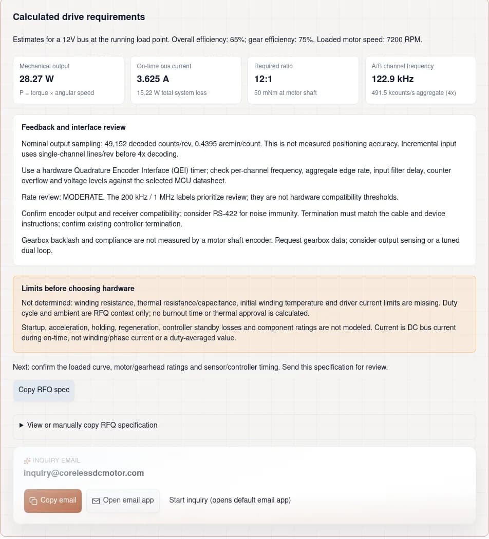
Assumptions: 600 RPM, 450 mNm, 65% overall efficiency; 7200 loaded motor RPM.
Calculation: 28.27 W output; 3.625 A on-time bus current; 12:1 ratio.
ABZ requirement: 122.9 kHz/channel, 491.5 kcounts/s aggregate.
Decision: request matched motor/gearhead ratings and controller compatibility. Accuracy and thermal suitability remain unconfirmed.
High-Speed Optical Scanner
Assumptions: 12000 RPM, 12 mNm, 78% overall efficiency; 12000 loaded motor RPM.
Calculation: 15.08 W output; 1.611 A on-time bus current; 1:1 ratio.
ABZ requirement: 102.4 kHz/channel, 409.6 kcounts/s aggregate.
Decision: request matched motor/gearhead ratings and controller compatibility. Accuracy and thermal suitability remain unconfirmed.
Precision Lead Screw Feeder
Assumptions: 250 RPM, 1200 mNm, 70% overall efficiency; 5000 loaded motor RPM.
Calculation: 31.42 W output; 3.74 A on-time bus current; 20:1 ratio.
Absolute serial timing is undetermined. Confirm sensor update rate and frame format.
Decision: request matched motor/gearhead ratings and controller compatibility. Accuracy and thermal suitability remain unconfirmed.
What the evidence establishes—and what is unknown
| Topic | Status | Boundary | Reference |
|---|---|---|---|
| Power and ratio | Calculated from stated assumptions | P = torque × angular speed. Efficiency is entered by the user; no motor curve is validated. | FAULHABER: DC-Motors — Technical Information |
| ABZ pulse rate | Calculated for incremental only | Per-channel cycles = RPM × lines / 60; aggregate 4x rate is four times this. MCU/filter bandwidth is unknown. | Texas Instruments: eQEP Module Reference Guide (SPRU790D) |
| Absolute serial bandwidth | Not determined | Needs clock, frame length, sensor update/processing time, latency and protocol variant. | BiSS Association: BiSS Interface |
| Stall, temperature and life | Supplier confirmation required | No winding resistance, thermal model or measured life test has been supplied. No safe-stall duration is inferred. | FAULHABER: DC-Motors — Technical Information |
| Cable reach and termination | Installation validation required | Select transceiver/cable together and measure receiver signals during PWM and braking. | Texas Instruments: RS-422 and RS-485 Standards Overview (SLLA070D) |
No supplier has confirmed a purchasable assembly for your inputs. The calculated ratio is kinematic, efficiency is assumed, and motor-shaft sampling through a gearbox is nominal. Use a rated brake where safe holding is required; do not assume a worm drive self-locks.
Misuse, cost and application risks
| Risk | Impact | Mitigation or alternative |
|---|---|---|
| Stall or repeated overload | Winding, driver or gearbox damage | Obtain current/thermal ratings; validate protection and acceleration/holding loads. |
| Wrong PPR/CPR convention or interface | Fourfold count error or incompatible controller | Confirm one-channel lines for ABZ and position words for absolute; match input voltage and protocol. |
| High resolution mistaken for accuracy | Load misses position despite fine displayed counts | Specify measured load error and repeatability; improve mechanics or use tuned load feedback. |
| Controller/cabling/commissioning cost omitted | Prototype cost and schedule overrun | Get a complete assembly and integration quotation, MOQ and lead time. |
| Speed or holding requirement mismatched | Overspeed, poor settling or backdriving | Check every mechanical rating; revise ratio/load point or add a rated brake. |
Engineering questions by decision
Power and operating point
Can 12V deliver both 10,000 RPM and 500 mNm?
That operating point requires 523.6 W of mechanical power. At an assumed 75% bus-to-shaft efficiency it draws about 58.2 A from 12V. These calculations do not establish a motor size or a thermal rating: obtain a loaded speed-torque curve, current limit and cooling specification.
Is candidate motor speed the no-load speed?
Enter the loaded motor speed at the required torque. A catalog no-load speed cannot be substituted: speed falls under load and may not reach the required operating point on the available bus voltage.
Does a gearbox increase available mechanical power?
No. It exchanges speed for torque and introduces losses. At ratio i and gearbox efficiency eta, required motor torque is load torque divided by i × eta. Verify input speed and output torque ratings separately.
What does the 12V current estimate include?
It is on-time DC bus current, P_output / (12 × assumed overall efficiency). It is not startup, locked-rotor or BLDC phase current. Include driver losses in overall efficiency if known; otherwise the estimate excludes them.
Should I choose brushed coreless or BLDC?
Compare commutation life, controller cost, torque ripple, envelope and the actual load cycle. Brushed coreless simplifies the drive; BLDC removes brush wear but needs electronic commutation. No single RPM or life threshold decides every application.
Can the tool predict safe stall time or approve intermittent duty?
No. Stall current and winding heating need winding resistance, driver behavior, initial temperature and thermal parameters. Duty percentage alone omits on/off duration and starting losses. Obtain supplier limits and validate protection with the actual motor.
Encoder resolution and interface
How should I enter PPR, LPR or CPR?
For incremental ABZ, enter cycles on one channel per shaft revolution, before decoding. This page calls that lines/rev or PPR; 1,024 lines produces 4,096 counts with 4x decoding. CPR is ambiguous across vendors: divide a specified 4x count by four before entry.
How is an absolute encoder entered?
Enter distinct positions per sensor revolution, for example 4,096 for 12-bit resolution. No 4x multiplier applies. BiSS-C/SSI clock and frame rate need protocol and device timing; the tool intentionally leaves serial bandwidth undetermined.
Does high nominal resolution guarantee positioning accuracy?
No. Quantization, sensor accuracy, mounting error, backlash, compliance and tuning are different limits. A calculated arcmin/count is only nominal sampling, not measured accuracy or repeatability.
Should the encoder be on the motor or output shaft?
Motor sensing gives more nominal counts per output turn through reduction but cannot measure gearbox motion errors. Output sensing observes load angle and may require more resolution for low-speed velocity estimation. A tuned dual loop combines both.
When can GPIO interrupts miss encoder counts?
When the worst-case event rate exceeds the measured interrupt service budget. There is no universal 20–50 kHz cutoff. Hardware quadrature decoding reduces software load, but its input timing and filter settings still require verification.
How should a timer input filter be checked?
Compare device-specific sampling and qualification delay with minimum valid pulse widths, including phase and duty-cycle tolerances. The aggregate edge interval is 1/f_edge; channel high/low time is approximately 1/(2f_channel) for ideal square waves. Do not infer a universal filter setting from this tool.
STMicroelectronics: Introduction to timers for STM32 MCUs (AN4013 Rev 14, February 2026)
Wiring, noise and PWM
Is RS-422 mandatory beyond a fixed cable length?
No universal length applies. FAULHABER describes possible incremental runs without a line driver up to 1–2 m, conditional on PWM and cable installation. Differential signaling can extend reach and noise margin; validate the selected transmitter, cable and receiver together.
Must every differential pair have a 120-ohm resistor?
Follow the driver/receiver instructions and match required termination to cable characteristic impedance. A 120-ohm load is an example for a matching cable, not a rule for every link. Check whether the controller already includes termination.
Texas Instruments: RS-422 and RS-485 Standards Overview (SLLA070D)
Does differential signaling cancel all PWM noise?
It rejects common-mode interference only within the receiver limits. Coupling asymmetry, poor routing, excessive common-mode voltage and reflections can still cause errors. Inspect waveforms at the receiver during worst-case motor switching.
Texas Instruments: RS-422 and RS-485 Standards Overview (SLLA070D)
What PWM frequency should a coreless motor use?
Select frequency using motor inductance, current ripple, driver losses, acoustic requirements and manufacturer guidance. Higher frequency often reduces ripple but raises switching losses. The Portescap paper describes this trade-off; no single range fits all windings.
How should encoder power and grounding be designed?
Respect sensor supply and receiver voltage limits; provide local decoupling and controlled return paths. Choose shielding, bonding and isolation for the installation. Test for supply dips and regeneration during acceleration and braking.
Texas Instruments: RS-422 and RS-485 Standards Overview (SLLA070D)
Mechanics, thermal limits and procurement
Does an output encoder eliminate gearbox backlash?
It measures the load position but leaves the physical gap and compliance in the plant. Validate reversal behavior and settling. Dual-loop tuning and suitable mechanical design can reduce their effect on positioning.
Are optical encoders always slower than magnetic encoders?
No. The maxon ENX 16 RIO example supports up to 40,000 RPM at specified resolution. Compare each sensor’s maximum shaft speed, output bandwidth and accuracy at the chosen resolution rather than assuming a technology-wide ceiling.
maxon: Advantages and practical applications of high-resolution encoders
Which thermal and duty information must a supplier confirm?
Request continuous and transient current, winding temperature limit, thermal resistance/time constants, mounting and cooling conditions, on/off times, starting frequency and ambient range. A duty percentage alone does not define S3 duty or permissible overload.
Does a single-turn absolute motor encoder retain gearbox output position after power loss?
It reports motor angle within one turn. Multiple motor revolutions can correspond to different output positions with the same reported angle. Use suitable multiturn sensing, output sensing or a homing/reference strategy for unambiguous load position.
What should I request before committing to a prototype?
Ask for a matched 12V loaded operating point, exact gear ratio, encoder interface and bandwidth, mechanical envelope, bearing loads and a tested duty cycle. Also confirm controller compatibility, integration cost, sample price, MOQ and lead time; this page provides no live quotation.
Sources and the next engineering review
Sources reviewed 2026-10-25. Publication/revision dates are included where the source states them.
Send the calculated RFQ with your loaded operating point, acceleration/holding torque, exact duty timing, envelope, bearing loads, required accuracy and cable layout. Request a 12V curve, motor/gearhead limits, encoder datasheet, compatible controller, sample quotation and validation plan. If inputs are unavailable, use the blank inquiry checklist.
- FAULHABER: DC-Motors — Technical Information
Motor equations, loaded operating points, commutation and model-specific thermal parameters. Does not establish a universal safe stall duration.
- maxon: Dual Loop Control — No more Gear Backlash
Motor and load feedback, cascaded loops, gain scheduling and resonance filtering. Performance requires commissioning.
- FAULHABER: Encoder Support
Resolution versus accuracy, available interfaces and cable installation considerations. No universal 25 cm TTL limit.
- Texas Instruments: eQEP Module Reference Guide (SPRU790D)
Quadrature decoding, index signals, position counters and edge capture. MCU timing limits remain device-specific.
- Portescap: Controlling Brushed DC Motors Using PWM (2019)
PWM frequency, current ripple and motor life trade-offs; not a blanket frequency prescription for every motor.
- maxon: Advantages and practical applications of high-resolution encoders
ENX 16 RIO optical encoder example: manufacturer reports up to 40,000 RPM at selected resolution and a 3 MHz output pulse limit. This is sensor data, not a complete 12V drive rating.
- STMicroelectronics: Introduction to timers for STM32 MCUs (AN4013 Rev 14, February 2026)
Timer modes and encoder interfaces. Use the exact MCU reference manual for filter sampling and maximum input rates.
- Texas Instruments: RS-422 and RS-485 Standards Overview (SLLA070D)
Balanced signaling, cable characteristics and receiver-end termination matched to cable impedance; 120 ohms is not universal.
- BiSS Association: BiSS Interface
Clocked sensor frames, data length, CRC, delay compensation and sensor processing time. Serial timing is separate from ABZ edge counting.
Ready to Prototype Your 12V High-Speed / High-Torque Drive?
Send your speed, torque, duty timing and encoder requirements for an engineering review and a prototype quotation.