
1. What to decide before buying a 12V vibration motor
Start with running RPM and unbalance
A voltage label cannot determine force. Compare mr and running speed first. Precision Microdrives: AB-004
Separate force from mounted response
Ideal G is a screening estimate. Supports can change motion substantially. Precision Microdrives: AB-030
Match the electrical interface
Identify a brushed motor, integrated BLDC or external-inverter BLDC before choosing drive and braking. Precision Microdrives: AB-018
Treat qualification as a separate decision
Use current limits and thermal validation; human exposure requires measured contact-point data. Texas Instruments: DRV8251; UK Health and Safety Executive: Guidance on measurement and monitoring
2. Method, units and limits
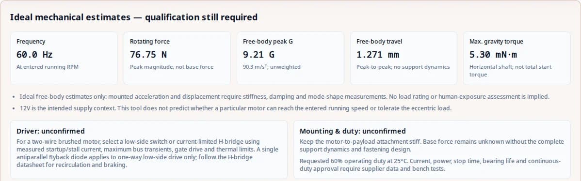
The tool assumes a single equivalent rotating unbalance and a translating assembly with negligible support stiffness and damping. It uses entered running RPM, not a speed inferred from 12V. Free-body motion is an ideal approximation; motor reachability and structural response are unconfirmed.
| Output | Equation | Interpretation / limitation |
|---|---|---|
| Frequency | f = n / 60 | One force cycle per shaft revolution; use running RPM. |
| Centrifugal force | F = m · r · ω² | Peak rotating-force magnitude; m in kg, r in m, ω = 2πn/60. |
| Free-body acceleration | a = F / M; G = a / 9.80665 | Ideal translating assembly; no spring, damping, resonance or human frequency weighting. |
| Free-body displacement | Dpp = 2mr / M | Ideal peak-to-peak travel; convert m to mm. Not a mounted displacement prediction. |
| Gravity torque | Tg,max = m · g · r | Worst gravity orientation for a horizontal shaft; excludes friction and spin-up torque Jα. |
The force and free-body equations follow Precision Microdrives: AB-004. The maximum gravity torque is derived from lever-arm statics. The 10% eccentric-mass flag is an editorial screening rule, not a manufacturer or standards limit.
3. Speed changes force faster than frequency
| Running speed | Frequency | Rotating force | Force relative to 3,600 RPM |
|---|---|---|---|
| 1,800 RPM | 30 Hz | 19.19 N | 0.25× |
| 3,600 RPM | 60 Hz | 76.75 N | 1.00× |
| 7,200 RPM | 120 Hz | 306.98 N | 4.00× |
Use this relationship to explore targets, then ask whether the motor and bearings can support the resulting radial load. Changing drive voltage or PWM may change running speed; it does not guarantee that an entered target is achievable. Precision Microdrives: AB-004
4. Compare architectures against the same requirement
| Architecture | Candidate reason | What to verify | Trade-off / limitation |
|---|---|---|---|
| Coreless brushed ERM | Consider for low rotor inertia | Validate rise/stop response with the actual eccentric load. | Brush life and radial load depend on the specific model. |
| Iron-core brushed ERM | Consider a simple two-wire drive | Check current, commutation and bearing capacity. | Rotor inertia and brush wear require supplier data. |
| BLDC ERM | Consider when brush wear is a concern | Identify integrated electronics versus an external inverter. | Supply reversal/PWM may be prohibited; life is not guaranteed by topology. |
| Dual-shaft adjustable ERM | Consider adjustable equivalent unbalance | Obtain weight-setting and shaft-load drawings. | Two ends do not automatically cancel bearing loads or guarantee an IP rating. |
Brushless designs remove brush wear, but bearings, controller temperature and weight loading still matter. A topology name is not evidence for a service-life guarantee. Precision Microdrives: AB-018
5. Adjustable weights: use equivalent unbalance
The vector relation shown is a geometric derivation for two equal unbalances in one plane. Enter an equivalent mass/radius pair with the same resultant mr. Do not assume opposed weights at separate shaft ends eliminate rocking moments. Ask the supplier for the actual weight-setting and shaft-layout drawing.
6. Driver and protection depend on the motor interface
| Interface | Known principle | Required check |
|---|---|---|
| One-way brushed low-side switch | A correctly oriented recirculation diode can clamp the inductive load. | Confirm stall current, diode pulse/average ratings, bus transients, gate drive and heat removal. |
| Brushed H-bridge | Coast, short-circuit brake and reverse drive are different modes. | Use the driver truth table and current limits. A single diode across the motor is incompatible with bidirectional drive. |
| BLDC with integrated driver | Power leads supply electronics; interface varies by motor. | Do not reverse polarity or PWM the supply unless explicitly allowed. |
| BLDC without integrated driver | Requires compatible phase commutation electronics. | Specify sensors, phase current and controller compatibility; a single low-side MOSFET cannot commutate it. |
Use an actual driver datasheet for current regulation, supply limits, switching and thermal calculations. Texas Instruments: DRV8251 is an example of the needed information, not a universal match. Precision Microdrives: AB-018 explains why supply reversal and supply PWM cannot be assumed for integrated BLDC motors.
7. Braking needs a measured current and time envelope
Coasting removes drive torque. Dynamic braking uses an electrical current path to oppose motion. Active reverse drive is another mode and must end before it accelerates the motor backwards. Measure stopping behavior at the actual inertia and temperature; no fixed milliseconds or percentage improvement can be inferred here. Precision Microdrives: AB-002
For a brushed system, capture current, speed and bus voltage during the supported braking mode. Use the controller current limit and account for returned energy where applicable. For a BLDC system, use its specified braking interface. Texas Instruments: DRV8251
8. Mounted response and human exposure are separate checks
A rigid motor attachment can help the motor and payload move together. Support stiffness and damping determine how that assembly interacts with the base; rubber alone does not establish a transmission ratio. Test the installed system through startup and its intended operating speeds. Precision Microdrives: AB-030
For hand-contact applications, do not compare this tool’s peak unweighted G with daily exposure values. ISO: ISO 5349-1 covers measurement and assessment. In the UK workplace context, UK Health and Safety Executive: Employers’ responsibilities gives 2.5 m/s² A(8) as the action value and 5 m/s² A(8) as the limit value; these are jurisdiction-specific daily exposure values, not instantaneous motor limits. Evidence checked 2026-10-25.
9. Thermal and bearing qualification cannot come from force alone
Supply running/startup/stall current, on/off durations, starts per hour, ambient and installed cooling conditions. A requested 100% operating duty does not assign an S1 rating. Validate winding and driver temperature in the intended enclosure; an IP rating describes ingress protection rather than thermal capability. Driver thermal calculations require the specific device and board. Texas Instruments: DRV8251
For bearings, obtain the bearing type, dynamic rating, radial/axial loads, overhang and operating conditions. Centrifugal force is not automatically the load on each bearing. Do not choose clearance, grease or a life-hour claim from RPM alone. These product-specific values remain unconfirmed.
10. Four worked bench concepts
These are illustrative inputs evaluated by the same calculator, not customer case studies, clinical evidence or measured test results. Each scenario provides a next test rather than a promised application outcome.
| Concept / inputs | Frequency | Force | Ideal G | Next validation |
|---|---|---|---|---|
| Steering assembly bench concept 4200 RPM; 25 g; 8 mm; 1.20 kg | 70.0 Hz | 38.69 N | 3.29 G | Compare a 1.2 kg assembly at 4,200 RPM. Measure the mounted pulse and bus transients before considering vehicle use. |
| Powder chute bench concept 3200 RPM; 150 g; 18 mm; 5.00 kg | 53.3 Hz | 303.19 N | 6.18 G | Compare a 5 kg chute with 150 g equivalent unbalance at 18 mm. Material flow, shaft load and thermal performance remain to be tested. |
| Isolated BLDC test platform 2400 RPM; 75 g; 14 mm; 2.20 kg | 40.0 Hz | 66.32 N | 3.07 G | Compare a 2.2 kg platform at 2,400 RPM. The mount does not supply an attenuation factor; measure the support response and confirm the BLDC interface. |
| Simulator pedal bench concept 5500 RPM; 35 g; 10 mm; 0.45 kg | 91.7 Hz | 116.10 N | 26.31 G | Compare a light 0.45 kg pedal at 5,500 RPM. Check acceleration at the foot contact and guard the rotating weight. |
11. Known, unknown and the minimum RFQ package
| Decision | Evidence available here | Minimum next action |
|---|---|---|
| Current and power | Unknown from geometry and RPM alone | Measure running/startup/stall current at defined bus voltage and mounting. |
| Mounted/base force | Unknown without stiffness, damping and support geometry | Measure frequency response and force/acceleration at the relevant contact points. |
| Stop time | Unknown without inertia, motor constants and brake current | Record coast/brake tests under current and temperature limits. |
| Thermal duty / S1 | Unknown; requested operating duty is only an RFQ input | Provide on/off cycle times, winding limits, ambient, enclosure and thermal test data. |
| Bearing life | Unknown without bearing ratings and load distribution | Obtain bearing type, shaft overhang, radial load, lubrication and life calculation. |
| Exposure compliance | Unknown; peak unweighted G is not A(8) | Use contact-point frequency-weighted RMS acceleration and exposure duration. |
Send your calculated summary, dimensional drawing, voltage envelope and quantity. Ask the supplier to return speed/current curves, permitted eccentric load at the actual overhang, interface details, life-test conditions, thermal data, price and lead time. Without a candidate motor datasheet, the minimum useful step is a feasibility review of these targets.
12. Risks, costs and alternatives
| Risk | Consequence | Mitigation / alternative |
|---|---|---|
| Misuse: substitute a 3V coin motor on a 12V rail | Electrical overstress and loss of the motor | Use a motor rated for the full supply envelope, or a compatible regulated driver. |
| Scenario mismatch: select by calculated G alone | Fixture resonance or a failed flow/haptic objective | Test actual moving mass, mounting and contact point; consider a tuned LRA/voice-coil if a precise waveform is essential. |
| Mechanical: exposed eccentric weight or excessive overhang | Contact, ejection, shaft or bearing damage | Guard the weight and obtain shaft-load/retention approval before operation. |
| Cost: buy for an unsupported life-hour target | Replacement, downtime and controller redesign costs | Compare qualified life tests and total maintenance costs; request brushed and BLDC quotations against the same duty. |
| Thermal: assume 100% requested duty proves continuous operation | Overheated winding or driver | Verify thermal equilibrium in the installed enclosure; use current and temperature protection. |
For direct 12V use, confirm the motor’s full permitted voltage range. For a tightly controlled haptic waveform, compare a suitably driven LRA or voice-coil concept and its controller requirements before committing to an ERM. For a large chute, request an industrial vibrator rated for the required load and duty rather than extrapolating a miniature motor.
13. Engineering and sourcing questions
Sizing and interpretation
What does this 12V DC vibration motor calculator actually predict?
It converts running speed and eccentric geometry into frequency and rotating force, then gives ideal free-body acceleration, travel and maximum gravity torque. It does not select or qualify a motor.
Does a 12V rating determine motor RPM?
No. Enter measured or supplier-specified running RPM at the actual supply and load. Voltage, winding, controller and mechanical load all affect speed.
Which mass belongs in the moving assembly field?
Include the motor, eccentric weights, fixture and payload that move together. Exclude a stationary support frame. If different parts flex independently, use a structural model or measure the response.
Is eccentric radius the outside radius of the weight?
No. Use the distance from the shaft axis to the eccentric mass center of gravity. The outside radius generally overstates the unbalance.
Why does doubling speed quadruple force?
F = mrω², so twice the running speed produces four times the rotating-force magnitude for unchanged mass and radius. The motor may not be capable of that operating point.
Is the reported G a peak or RMS value?
It is an ideal free-body peak estimate. It is neither measured mounted acceleration nor a frequency-weighted exposure value.
Why can displacement stay constant when I change speed?
In the ideal free-body model, F grows with ω² while displacement is F/(Mω²), leaving Dpp = 2mr/M. Stiffness, damping and resonance change the mounted response.
Is maximum gravity torque the motor starting-torque requirement?
It is only one contribution for the worst orientation of a horizontal shaft. Add friction and the torque needed to accelerate total inertia. A vertical shaft has a different gravity contribution.
Driver and supply decisions
Can the tool size my power supply or MOSFET?
No. Geometry and running speed do not determine electrical current. Use motor current curves or measurements, startup/stall current, supply transients and thermal limits to select the driver and supply.
Does every vibration motor need a diode directly across its terminals?
A single antiparallel diode is appropriate for a one-direction brushed low-side switch. An H-bridge uses its specified recirculation paths; a single terminal diode would obstruct reverse drive. BLDC electronics require their own datasheet guidance.
Can I reverse a BLDC vibration motor to brake it?
Do not reverse the power leads of a BLDC motor with integrated electronics unless its manufacturer explicitly allows it. Use only supported controller braking commands. Brushed H-bridge braking advice does not transfer to BLDC supply pins.
Which PWM frequency should I use?
Use the permitted range for the specific motor and driver, then check current ripple, acoustic response, startup and switching losses. Shaft RPM alone does not determine a suitable PWM frequency.
How fast will my motor stop with active braking?
Stop time is unknown until motor constants, inertia, braking current and control logic are specified. Measure coast, dynamic brake and any reverse-brake mode under the actual eccentric load.
Does 12V nominal mean direct automotive-battery compatibility?
No. Specify minimum and maximum voltage, startup dips, charging conditions and electrical transients for the application. A nominal voltage label is not a vehicle qualification.
Mounting, qualification and purchasing
Will rubber mounts always reduce vibration?
No. A mount can amplify response near resonance. Measure support natural frequency and damping and validate the complete assembly instead of assuming a fixed attenuation percentage.
Can 100% operating duty be treated as an S1 continuous rating?
No. It is a requested on/off duty. Continuous operation needs thermal qualification with the real motor, enclosure, cooling and ambient. Include cycle durations and starts per hour in the RFQ.
Can the calculator prove safe hand-arm vibration exposure?
No. Use frequency-weighted RMS vibration at the hand contact and actual exposure time. ISO 5349 describes assessment methodology; UK HSE explains the applicable workplace action and limit values. The calculator peak G is not comparable directly.
Do the presets demonstrate validated automotive or medical performance?
No. All four presets are illustrative bench concepts. They are not customer results, clinical evidence or safety qualifications; their mounted behavior remains to be tested.
How do I enter two adjustable eccentric weights?
For weights acting in the same transverse plane, combine their unbalance vectors. Two equal unbalances u at phase angle θ have a resultant magnitude 2u|cos(θ/2)|. Separated shaft ends can also create a couple; obtain the manufacturer setting diagram.
Can bearing life be calculated from centrifugal force alone?
No. Bearing type, dynamic rating, equivalent bearing load, speed and operating conditions are needed. Shaft overhang changes load sharing; use the bearing manufacturer method and a complete shaft layout.
How should I compare brushed and brushless quotes?
Use the same speed, equivalent unbalance, bus envelope, mounted duty and environmental requirements. Compare controller cost, qualification evidence, service intervals and replacement effort rather than generic life-hour claims.
What if copying the RFQ is blocked by my browser?
Select and copy the visible RFQ text manually, download the text file, or open the prefilled email. These paths retain the assumptions and the supplier data still required.
14. Primary sources and evidence scope
Sources were checked on 2026-10-25. Manufacturer notes support principles within their stated scope; they do not validate these 12V bench concepts. No public evidence is claimed for model-independent life hours, current multipliers, grease prescriptions or guaranteed braking times.
- AB-004: Understanding ERM Vibration Motor Characteristics
Precision Microdrives · Checked 2026-10-25. ERM force and simplified motion model. General mechanics; does not qualify a 12V product.
- AB-030: Extending Vibration Theory — Displacement and Dissipation
Precision Microdrives · Checked 2026-10-25. Mount stiffness, damping and model boundaries. Does not supply a universal isolation percentage.
- AB-002: Discrete H-Bridge for Enhanced Vibration Control
Precision Microdrives · Checked 2026-10-25. Brushed ERM braking principles. Timing and component choices are specific to the tested motor and circuit.
- AB-018: Driving Brushless Long-Life Vibration Motors
Precision Microdrives · Checked 2026-10-25. Integrated BLDC driver restrictions, including supply PWM and reversed supply polarity.
- DRV8251: Brushed DC Motor Driver with Integrated Current Regulation
Texas Instruments · Checked 2026-10-25. Example primary datasheet for brushed H-bridge modes, current regulation and thermal design. Not an automatic part recommendation.
- ISO 5349-1:2001 — Hand-transmitted vibration, general requirements
ISO · Checked 2026-10-25. Public scope of the measurement and evaluation standard; no exposure compliance is inferred here.
- Employers’ responsibilities: hand-arm vibration exposure
UK Health and Safety Executive · Checked 2026-10-25. UK workplace context: daily action value 2.5 m/s² A(8), limit value 5 m/s² A(8). These are not raw motor acceleration limits.
- Guidance on measurement and monitoring
UK Health and Safety Executive · Checked 2026-10-25. Representative contact-point measurements and competent assessment; measured conditions can vary.