
Integrated Miniature Encoders for Coreless DC Motors: Sourcing Guide for Optical, Magnetic, and Inductive Feedback (2026)
Compare integrated coreless motor encoders: optical, magnetic and inductive feedback, count rates, backlash and validation. Prepare your OEM sourcing RFQ for 2026.
Sourcing decision: Choose an integrated coreless motor encoder by required motor speed feedback, output positioning error, controller bandwidth, and installation environment. Higher counts improve sampling resolution but cannot measure gearbox lost motion from the motor side.
Published and technically reviewed: 26 October 2026. Scope: global OEM sourcing of miniature brushed coreless and brushless slotless motor assemblies, primarily below 32 mm diameter. This is a catalog-based engineering decision framework, not a hardware test report or a market price survey. Numerical examples are illustrative calculations; confirm each ordered assembly's ratings and availability with its supplier.
For robotic grippers, dosing pumps, camera gimbals, and inspection stages, engineers and buyers need to avoid two specification traps:
- Buying resolution as accuracy: More encoder counts do not establish angular accuracy, load-side repeatability, or compensation for gearbox backlash.
- Choosing by sensor price alone: A compact encoder still needs a compatible receiver, harness, thermal design, and a documented acceptance test. Those integration costs belong in the quote comparison.
Preparing a purchase specification? Start with the coreless motor RFQ checklist, then use the feedback matrix and worked example below to fill in the encoder requirements.
The Feedback Dilemma: Balancing Size, Cost, and Accuracy
On a miniature motor, the encoder, connector, target, and cable bend radius compete for limited space. Compare the complete assembly drawing rather than the sensor IC dimensions.
- Axial length: Obtain total motor-plus-encoder length, connector clearance, and permitted shaft projection. A short PCB does not guarantee a short installed package.
- Rotor inertia: Request target or disc inertia when acceleration matters. Brushed coreless motors have a rotating ironless winding; brushless slotless motors use a different rotor construction. Do not transfer inertia assumptions between them.
- Thermal and electrical proximity: Measure temperature at the encoder location under the intended duty cycle. Validate signal integrity with the actual drive, cable routing, receiver, and grounding arrangement.
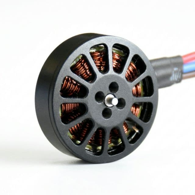
The cover photograph illustrates motor packaging; it does not expose or verify a particular encoder implementation.
Architectural Comparison: Optical vs. Magnetic vs. Inductive
To make a defensible sourcing choice, buyers must look beyond headline resolution numbers on catalog datasheets and evaluate how each technology operates under real-world factory assembly and environmental stresses.
1. Miniature Optical Encoders
Optical encoders read a patterned disc using a light source and photodetectors. Transmission and reflection arrangements are both used.
- Operating principle: Light modulation is converted into position signals, commonly incremental A/B quadrature and an optional Z index.
- Procurement advantages: Optical sensing avoids magnetic disturbance of the measurement principle. Consider it when angular error and smooth low-speed feedback matter; request measured accuracy, repeatability, and timing rather than choosing by line count alone.
- Sourcing constraints: Confirm contamination protection, disc alignment, shock rating, and the complete assembly's temperature rating. Optical products can use interpolation, and their electronics and harness remain susceptible to electrical noise. FAULHABER's encoder overview explains the optical/magnetic distinction and signal interpolation; it does not establish a universal technology ranking.
2. On-Axis and Off-Axis Magnetic Encoders
Magnetic micro-encoders read a rotating magnetic target with Hall or magnetoresistive sensors. Target geometry and sensor placement depend on the specific design.
- Operating principle: Electronics convert the sensed field angle into incremental or absolute feedback. A/B/Z, SPI, SSI, or BiSS-C availability is product-specific; these interfaces are not interchangeable.
- Procurement advantages: Compact integration and tolerance of dirt at the sensing interface can suit geared actuators and portable equipment. The completed PCB, connector, and enclosure still need an environmental rating.
- Sourcing constraints: Request permitted external-field strength, target alignment and air-gap limits, latency, and angle-error data. Test at intended motor current and with nearby brakes energized. Shielding is one possible mitigation; neither a shield nor a particular alloy is mandatory for every design.
3. Planar Inductive Micro-Encoders
Inductive encoders detect angle through electromagnetic coupling between stationary coils and a rotating conductive target.
- Operating principle: Excitation and receiving coils sense angle-dependent changes in coupling, which electronics convert into feedback.
- Procurement advantages: This architecture can resist magnetic interference and dirt at the sensing interface. The maxon MILE EC 45 flat product information documents an inductive implementation with differential A/B outputs (printed pp. 3–6).
- Sourcing constraints: That document describes a larger EC 45 flat assembly, not availability for a sub-32 mm coreless motor. Its encoder operating range is −40°C to +100°C, with condensation prohibited (p. 4). Inductive sensing alone establishes neither a 150°C assembly rating nor steam-sterilization suitability. Confirm miniature packaging, target clearance, and qualification before shortlisting a vendor.
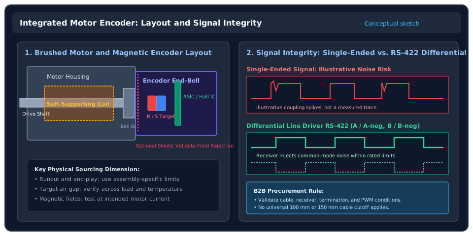
Engineering Visual: Architecture & Commutation Noise Coupling
This conceptual sketch shows a brushed coreless motor with rear magnetic feedback and two signal-interface options. It is not a dimensional drawing or a measured waveform. The comparison concerns the electrical interface; any sensing technology can require noise mitigation. Scroll horizontally on small screens to read the labels.
9-Dimensional Sourcing Matrix
Use this matrix to request comparable evidence. Entries describe selection questions, not guaranteed ratings or market-wide price ranges.
| Selection Dimension | Miniature Optical Encoder | Integrated Magnetic Encoder | Planar Inductive Micro-Encoder |
|---|---|---|---|
| 1. Sensing mechanism | Light source, patterned disc, detector | Magnetic target and Hall or magnetoresistive sensor | Excitation/receiving coils and conductive target |
| 2. Resolution specification | State output cycles/rev and any interpolation | Separate output resolution from angle accuracy | State output cycles/rev or absolute word length |
| 3. Jitter and latency | Request timing, interpolation error, and low-speed data | Request angle error versus field, speed, and temperature | Request angle error, demodulation latency, and jitter |
| 4. Magnetic and electrical disturbance | Optical principle resists magnetic interference; validate electronics | Validate external-field tolerance and motor-current effects | Verify specified magnetic rejection; validate electronics and harness |
| 5. Contamination | Protect optical path from deposits and condensation | Dirt tolerance does not establish PCB or connector sealing | Coil/target tolerance does not establish a sealed assembly |
| 6. Temperature | Use complete encoder assembly rating | Include magnet, adhesive, IC, and connector limits | Include PCB, ASIC, target, and connector limits |
| 7. Package and inertia | Request disc inertia, total length, and alignment limits | Request target inertia, air gap, and end-play limits | Confirm target clearance and miniature motor compatibility |
| 8. Commercial comparison | Quote assembly, alignment, testing, and NRE separately | Quote target mounting, calibration, and any shielding | Confirm standard versus custom design and tooling ownership |
| 9. Shortlist trigger | Positioning or speed performance supported by measured data | Compact integration with verified field tolerance | Field-resistant sensing with a qualified package and supplier |
Gearhead Backlash vs. Encoder Resolution: A Worked Example
Before comparing quotes, define the count convention. In this guide, P means electrical cycles per motor revolution on channel A, and C = 4P means decoded counts per motor revolution with x4 quadrature decoding. Vendors use CPR and PPR differently; require both quantities in writing.
Understanding the Backlash Floor
An encoder on the motor shaft measures the input of the gearbox. It cannot directly observe load-side movement inside gear clearance, compliance, or wear. Use the specified or measured output backlash under a defined load and direction reversal; do not infer it from gearhead diameter.
If load-side position during reversal is the acceptance criterion, consider an output encoder or a validated mechanical/control strategy. More motor counts can still improve motor velocity estimation and loop behavior; high resolution does not itself cause hunting or become useless merely because backlash exists.
Calculate Output Count Spacing and Input Frequency
Let i = motor revolutions / output revolutions and β be output backlash in degrees. The kinematic relations are:
Decoded motor counts/rev:       C = 4 × P
Output count spacing (degrees): Δθout = 360 / (C × i)
Motor angle across backlash:    βmotor = i × β
Decoded counts across backlash: nbacklash = β × C × i / 360
Channel-A cycle frequency (Hz): fA = P × motor_rpm / 60
x4 counter edge rate (edges/s): fcount = C × motor_rpm / 60
For a chosen quantization target q degrees at the output, the count requirement is C ≥ 360 / (i × q). This is a minimum resolution screen, not a maximum useful encoder size or a positioning-accuracy guarantee. Check sensor error, transmission error, compliance, and control bandwidth separately.
Illustrative inputs: i = 64, β = 1.5°, P = 256 cycles/rev,
                     x4 decoding, motor speed = 12,000 rpm
C = 1,024 decoded counts/motor rev
Δθout = 360 / (1,024 × 64) = 0.005493°/count
βmotor = 64 × 1.5° = 96° at the motor
nbacklash = 1.5 × 1,024 × 64 / 360 ≈ 273 decoded counts
fA = 256 × 12,000 / 60 = 51,200 Hz
fcount = 1,024 × 12,000 / 60 = 204,800 edges/s
Decision: This example has fine count spacing relative to its assumed backlash, but the output may still move within that backlash without corresponding motor rotation. Compare higher-resolution candidates using the required low-speed feedback performance and receiver limits. Verify 51.2 kHz per-channel cycles and 204.8 k edges/s decoded throughput against the controller's definitions; they are different limits. No hardware performance or supplier cost was measured here.
Quick Reference: Reproducible Resolution Examples
All rows are hypothetical, use x4 decoding, and exclude sensor and transmission errors. None is a motor or encoder recommendation.
| Reduction i | Channel-A cycles P/rev | Decoded motor counts C/rev | Output spacing (°/count) | Assumed output backlash β | Engineering implication |
|---|---|---|---|---|---|
| 1:1 direct drive | 256 | 1,024 | 0.351563 | No gearbox | Check spacing against the direct-drive target |
| 16:1 | 256 | 1,024 | 0.021973 | 1.5° | Count spacing does not establish reversal accuracy |
| 64:1 | 256 | 1,024 | 0.005493 | 1.5° | About 273 counts span the assumed lost-motion window |
| 64:1 | 1,024 | 4,096 | 0.001373 | 1.5° | Fourfold count rate; backlash remains unchanged |
| 100:1 | 64 | 256 | 0.014063 | 2.0° | Assess low-speed velocity estimation separately |
| 100:1 | 256 | 1,024 | 0.003516 | 2.0° | Finer spacing still cannot measure load-side play |
Use the 12V encoder motor speed, torque, and pulse-bandwidth tool to organize candidate operating points before requesting samples.
Sourcing Considerations: Factory-Integrated vs. Customer Assembly
A factory-integrated motor-encoder assembly can put alignment, harness testing, and warranty responsibility with one supplier. A modular kit can be appropriate when the OEM has the fixtures, process controls, and validation capability. Annual volume alone does not decide which approach is viable.
Compare total landed assembly cost using the same drawing revision, order quantity, test scope, warranty, currency, shipping terms, and quote date. Request motor and encoder prices, assembly labor, calibration, harness/receiver cost, NRE, expected scrap allowance, and sample versus production lead times separately. There is no universal optical or inductive price premium.
Three Assembly Risks to Assign Before Ordering
- Target alignment and shaft movement: Ask for permitted radial offset, runout, tilt, and axial end-play from the selected encoder drawing. Require evidence that the tolerance stack maintains the air gap at load and temperature extremes. A single micron-level limit cannot cover all sensor geometries.
- Pressing and retention: Obtain the motor maker's permitted assembly loads and support the shaft as specified. Define adhesive cure, target retention, and balance checks where applicable. Bearing load limits and suitable fixtures depend on the actual motor.
- Reference and commutation setup: For incremental feedback, agree direction, index availability, index gating, and the homing sequence. For BLDC control, separately define electrical-angle initialization and offset calibration with the controller supplier. A Z pulse is not universally required for FOC, and an index does not provide absolute position immediately at power-up.
Practical Procurement Checklist for RFQ Preparation
Engineering and purchasing should send one agreed specification and acceptance plan:
- Operating point: State speed range, load torque, acceleration, motor voltage, duty cycle, ambient temperature, and required low-speed behavior.
- Position requirement: Separate motor velocity control from load-side position accuracy and reversal repeatability; specify gearbox ratio, backlash conditions, and any output feedback.
- Resolution convention: State channel-A cycles/rev, x1/x2/x4 decoding, decoded counts/rev, and permitted angle error. For absolute feedback, specify single-turn versus multi-turn behavior.
- Protocol and receiver: Specify A/B with optional Z, analog sine/cosine, SPI, SSI, or BiSS-C as applicable. Include supply voltage, output stage, receiver thresholds, input frequency, and decoded counter throughput.
- Harness and noise: Define cable length, routing, flex life, connector pinout, shielding, grounding, and any termination. Consider differential outputs for noisy or extended runs, then qualify the complete link. There is no universal 100 mm or 150 mm single-ended cutoff. Texas Instruments SLLA556 explains the RS-422 rate/length and propagation-delay trade-offs; its particular circuit is not a motor-harness qualification.
- Thermal and environmental limits: Use measured encoder-location temperature and the complete assembly rating. A winding insulation class is not an encoder ambient-temperature requirement. Define condensation, ingress, shock, vibration, and any cleaning exposure separately.
- Mechanical integration: Obtain motor-plus-encoder dimensions, target inertia, mounting loads, runout, air-gap and end-play limits, and responsibility for calibration.
- Acceptance records: Agree sample sizes and production test coverage, with supplier-specific phase, duty-cycle, index, current-consumption, and error limits. Request serial/lot traceability and records of the agreed tests; do not impose invented universal limits.
- Supply continuity: Confirm sample MOQ, production MOQ, lead time, sensor lifecycle, change notification, tooling ownership, and an approved alternative strategy.
Sample Acceptance Plan
For each candidate assembly, log its part number, drawing revision, controller/firmware, cable, receiver, supply, temperature, and load conditions. Run forward/reverse motion, low-speed control, maximum intended speed, and the intended peak-current duty within component ratings. Check signal levels and minimum state duration at the receiver, count consistency against an independent reference, and load-side reversal error. Include nearby brakes or other field sources when present.
Agree allowable count discrepancies, velocity ripple, temperature, and positioning error before ordering samples. These are proposed qualification steps, not tests performed for this article; an oscilloscope trace alone does not prove mechanical accuracy.
Frequently Asked Questions (FAQ)
Q1: Are optical encoders always smoother at low speed than magnetic encoders?
No. Interpolation error, timing jitter, filtering, sensor alignment, and the controller's velocity estimator affect both. Compare low-speed results at the required speed, load, temperature, and estimator settings. Higher advertised resolution does not establish lower ripple.
Q2: What is the maximum cable length for single-ended TTL encoder signals?
There is no universal length. Driver strength, cable capacitance, edge rate, receiver thresholds, routing, grounding, and electrical noise determine the usable link. Start with the encoder and controller limits; evaluate differential signaling where needed and verify the receiver waveform and count integrity under actual motor switching conditions.
Q3: Can an encoder-equipped coreless motor withstand steam sterilization?
Only claim this for a complete assembly with a supplier validation report covering the intended cycle temperature, pressure, dwell time, drying process, chemicals, and cycle count. A high-temperature IC, sealed housing, or inductive measurement principle alone does not establish steam compatibility. Confirm motor bearings, adhesives, cable, and connector performance as well as the encoder.
Q4: What is the difference between CPR and PPR?
Suppliers use these abbreviations inconsistently. Here, P means complete channel-A electrical cycles per mechanical motor revolution, and C means decoded counts at the selected decoding factor. At x4, 256 cycles/rev yields 1,024 decoded counts/rev. A differential line driver improves signal transmission; it does not change the decoding factor. Put both numbers and the decoding mode on the RFQ.
Q5: How does shaft axial play affect a magnetic encoder?
Axial play changes the target-to-sensor gap and can alter field strength and angle error. Verify the permitted gap across bearing play, assembly tolerances, load, and thermal expansion using the selected sensor's limits. There is no universal 0.5 mm gap, 0.03 mm end-play requirement, or mandatory bearing type.
Q6: Does adding an encoder increase MOQ or lead time?
It can, especially for a custom target, PCB, harness, or calibration process. Stock integrated assemblies may have different terms. Request dated, quantity-specific quotes for bare motor and encoder assembly, separating sample availability, tooling time, and repeat-order lead time. Do not use generic MOQ or week ranges as supplier commitments.
Take the Next Step: Aligning Your Motor Feedback Architecture
Send your motor envelope, operating point, controller interface, harness length, gearbox data, annual quantity, and acceptance criteria to the application team. Ask which optical, magnetic, or inductive options are available for that package, which require development, and what evidence can accompany samples.
- Use our RFQ Checklist for Coreless DC Motor OEM Projects to prepare the specification.
- Check candidate speed, torque, and pulse rates with the 12V DC Motors with Encoders Engineering Guide.
- Contact our application team to confirm integration feasibility, documentation, sample terms, and a quotation for your required feedback architecture.
Sources & References
Source pages reviewed on 26 October 2026. Manufacturer specifications apply to the documented product and revision, not every miniature encoder. The sourcing matrix and calculations above are engineering synthesis; they are not independent product tests or price benchmarks.
- FAULHABER — Encoders for DC Micro Motors. Product overview covering optical/magnetic sensing, incremental/absolute feedback, quadrature channels, and interpolation. Does not support universal price, temperature, or jitter rankings.
- maxon — MILE Encoder for EC 45 flat, Product Information, edition 2020-07, DocID 1877473-07. Printed pp. 3–6 describe the inductive implementation and ratings; p. 7 distinguishes angle error, jitter, and state duration. This larger-motor example does not establish sub-32 mm availability or sterilization capability.
- Texas Instruments — SLLA556, RS-422 application brief, June 2021. See “Design Steps” for signaling rate versus cable length, delay, and termination considerations. Its circuit-specific distances and component choices are not encoder cable-length guarantees.
Author
Categories
More Posts

Coreless DC Motor Thermal Derating & NdFeB Magnet Sourcing Guide (2026)
A decision-grade sourcing guide for procurement teams addressing coreless motor thermal failures, NdFeB magnet demagnetization risks, and EU Critical Raw Materials Act (CRMA) compliance in 2026.

Precious Metal vs Graphite Brushes in Coreless Motors: OEM Sourcing Guide
A procurement-focused breakdown of coreless DC motor commutation options. Learn when to source precious metal vs graphite brushes to balance MTBF, duty cycle, and unit cost.
RFQ Checklist for Coreless DC Motor OEM Projects
A practical RFQ checklist to speed up technical alignment, quoting, and sample planning for custom coreless DC motor sourcing.